Despite playing with electronics for years, there’s a lot I didn’t know about the basics. I find that a good way to learn something and understand it well, is by explaining it to someone else. This article is the first of (hopefully) many, and kicks off with some simple concepts that are fundamental to all electrical systems.
- Introduction
- Assumptions
- What does “Analog Electronics” mean?
- What is an electrical circuit?
- Understanding Current, Voltage, and Resistance
- Bringing it all together with Ohm’s law
- Examples
- Conclusion
- Further Reading
Introduction
In these articles I hope not only to teach others, but reinforce my own understanding. If you think I’ve explained something incorrectly or poorly, please correct me. If I pass briefly over a topic that you feel really needs more detail, suggest a web link or a short addition that I can include here.
In studying electronics, you’ll learn about two models: “Analog Electronics” and then “Digital Electronics”. Both are valid, and have their own specific applications. This article gives a brief summary of analog electronics, and simple facts which are crucial to all electrical behaviour.
With an understanding of analog electronics, you will be able to examine and even design more complex systems, including the analog components and behaviours that affect, support, and drive digital systems.
I will avoid the physics of electronics, and some of the detailed theory. I am going to focus more on the practical side, so I can take you through these topics quickly. If you want the “nitty-gritty”, maybe take a look at the Further Reading section.
Assumptions
Even if the following concepts are all new to you, hopefully you will still be able to follow this article.
In these articles, I will assume that:
- You observe Electrical Safety – do not experiment with anything connected to mains power.
- You’ve had at least some basic hands-on experience with electricity, maybe just to light something up, install or fix some wiring, or charge a car battery – even if just from someone else’s instructions.
- You more-or-less know what “conductors” and “insulators” are;
- You know how to interpret at least the basics of circuit diagrams (i.e. schematics);
- Optionally, you know the difference between conventional current and electron flow.
What does “Analog Electronics” mean?
Commonly, “analog electronics” refers to designs that respect electricity as a continuous, variable quantity, where even small variations in electrical levels may be important, calculated, and used purposefully. These variations have a direct measurable effect on (and drive operation of) the system as a whole.
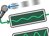
 Figure 1: Example of an analog system
 The word “analog” means “proportional”. This describes how “information” in the system is directly represented by varying electrical levels. For example, a microphone senses air pressure waves (sound), and may express the pressure as a tiny, proportional, electrical level. That electrical level can then be modified by an electronic device, to proportionally enlarge (amplify) it. The now-amplified signal may then be converted back into sound, by mechanically driving a loudspeaker.
All electrical systems are fundamentally analog in nature: The analog model describes electrical phenomena in continuous mathematical terms, and we’ll start with the simplest aspects of this.
What is an electrical circuit?
The following is an example of the simplest circuit, but don’t try assembling it as described because it has no limiting factors, and hence will have damaging effects.
Any work done by an electrical device, is because of “charge” flowing through it. “Charge” is like a quantity of electricity1, and is often visualised as a liquid. It can be made to “flow” in one direction or another through the material of a “conductor”, such as a metal. The solid of the conductor “contains” the charge in much the same way that the hollow inside a pipe can contain water.
 Figure 2: Simplest complete circuit
 If an electrical conductor is in direct physical contact with an electrical energy (“voltage”) source, electrical charge will flow at a given rate (“current”) so long as it has a return path. The amount of current is restricted by the imperfect nature of the conductor (“resistance”), which is usually deliberately controlled. This is a circuit, in that an energised charge can come from one place, follow a direct path, and return to another place – to be re-energised for as long as the energy supply lasts.
- Example conductor: A continuous piece of metal, such as a wire.
- Example voltage source: A battery, with two terminals. High-energy charge leaves via one terminal – call it “positive” (usually indicated by a plus () symbol or a red marking).
- With a battery, the return path is via the other terminal that receives charge that has spent its energy – call it “negative” (usually indicated by a minus () symbol, or a black marking).
Note that the source of energy (the positive end, which has the “higher relative voltage”) is sometimes said to “source current”, while the return path (the negative end, which has the “lower relative voltage”) is said to “sink current”.
 Figure 3: Simple lightbulb circuit
 Now, if a gap is created in the circuit (i.e. a cut and separation in the conductor)…
- And a suitably-chosen component (e.g. lightbulb) is inserted…
- Such that electrical charge is able to flow into one end of it…
- And flow out of the other end and back onto the return path…
…then a simple useful circuit has been created, as the current supplies energy that lights the bulb. It is the insertion of extra components and more paths between the voltage source’s positive and negative terminals that allows for creation of more complex circuits that perform useful tasks.
 Figure 4: A broken, or 'open' circuit
 Why is the circuit configuration (i.e. return path) necessary? A voltage source (battery) does not simply “leak” or eject charge as soon as a conductor is attached. Rather, energy is added to the charge as it passes through the voltage source. If there is no charge arriving at the negative end, then there is nothing to energise and push onwards. Hence, no current will flow.
In this sense, a voltage source is like a pump. You will notice in Figure 4 that the bulb is not lit because there is no current: Though a conductor path apparently joins a positive terminal with a negative one, there is no way to continuously get charge into (or out of) the batteries, and hence they have no effect.
WARNING: When mains power is involved, touching even one terminal may harm or kill you. The voltage is high enough that a lethal current can pass through your body and complete a circuit with the ground beneath you, even if it doesn’t appear that there’s a conductor path between you and the ground.
Understanding Current, Voltage, and Resistance
I’m not going to explain the details of what current, voltage, and resistance actually are at the physical level, but here’s a summary of how they’re the most fundamental characteristics of an electrical circuit:
Current
Denoted , “current” is an instantaneous measurement of the rate of flow of electric charge. It is because of current that there is activity in a circuit. It can be imagined that as current increases, a circuit becomes more “active” or more “energised”. Current is measured in “Amperes” (or “amps”, more commonly) – denoted A.
Resistance
Denoted , “resistance” is the property of an electrical component (or simple conductor) to restrict the flow of charge (i.e. to resist, and hence reduce, the current). It’s measured in “Ohms”, denoted Ω. With higher resistance, there will be less current.
Voltage
Denoted , or sometimes , “voltage” can be thought of as relative electrical “pressure” that encourages charge to flow (and hence “causes” current). More-formally it is a difference of electrical potential energy, between two points, that acts as a force to cause electrons to flow through a suitable conductor medium. Voltage is measured in “volts”, denoted V.
Bringing it all together with Ohm’s law
 Ohm's Law Triangle
 So, voltage causes current, but current is restricted by resistance. Ohm’s law explicitly states the inter-dependence between voltage (), current (), and resistance ():
When you have:
- Any pair of points in a circuit…
- That have a voltage difference between them (i.e. a difference in potential)…
- And are connected by an uninterrupted electrical path…
- For which, you can express a total equivalent resistance…
- With no other external voltage influences along that path…
…then there will be a current that is equal at all non-divided points along that path, and which can be calculated using Ohm’s law.
Examples
Very simple applications of Ohm’s law are demonstrated in the circuit diagrams below. Though these specifically use a known voltage and resistance to calculate current, you can use the identities of Ohm’s law with any two known variables to calculate the third unknown variable.
Though it appears most of these examples are not circuits, the presence of a voltage difference at points A and B implies that they’re connected to an unseen voltage source that completes the circuit. You can assume that the voltage source is a battery, power supply, or possibly even two points in a larger circuit.
 Figure 5: Example circuits demonstrating Ohm's Law
 Example 1
The total resistance between points A and B is shown to be 350Ω, while the voltage difference is 7V. So, the current from A to B (and at all points along the undivided path) is:
Hence, (20 milliamps) from A to B.
Example 2
The voltage difference between A and B is . We don’t know the respective resistances of R2 and R3, but if we were told that the total equivalent resistance is, say, 1kΩ between A and B, then:
Hence, from A to B. Again, because the path is undivided, this current is the same at all points along the path, including through each resistor, and the wire that joins them in the middle.
Example 3
In this example, there’s a different symbol at point B, which is the ‘ground’ symbol. It does not literally refer to the ground or “earth” beneath you, but rather indicates a reference point, which is always considered to be a relative 0 volts. Any points in a circuit that use this symbol are assumed to be directly connected to each other, and hence at the same reference voltage. Any other voltages are expressed as relative (positive or negative) to the ground 0-volt reference.
In this case, the voltage difference between A and B is . Again, we don’t know the resistances of the two resistors, but if we were told that the total equivalent resistance between A and B is, say, 2.4kΩ, then:
Hence, from A to B. The negative current simply indicates that the charge is flowing in the reverse direction, since . Note that in this case, because the path is divided, we can’t say that the current across R4 (or R5) individually is the same as across the whole path. However, we can say that the current across the pair of them is still . Ohm’s law also lets us conclude the following:
- The voltage at the top point where R4 and R5 are connected, is -6V.
- Likewise, the voltage at the bottom point where they’re connected is 0V.
- Given this, the voltage across each of R4 and R5 is known to be -6V (looking downwards).
- Hence, if we knew the resistances of R4 and R5 respectively, we could calculate their respective currents…
…and we would actually find that , which forms the basis of Kirchhoff’s Current Law, which is a topic for my next article.
Example 4
This circuit looks a little different from Example 3, but is basically the same configuration. Instead of being given explicit voltages for points A and B and having to find the difference, we can see that the voltage source BAT1 sets the voltage difference between these two points to 10V.
The ground symbol at the bottom doesn’t change anything, but establishes that we wish to consider this point to be our reference 0 volts, meaning that the relative voltage at A will be 10 volts. In larger circuits, this may be important to illustrate how multiple parts of the circuit are connected to the same baseline voltage.
If we were told that the equivalent resistance from A to B (through the network of resistors) was 80Ω, then the current from A to B is:
That is, the current through the whole loop from A to B is 125mA, which is hence the current through R6, and hence the current through the pair of R7 and R8.
Conclusion
By now you should understand the relationship between voltage, current, and resistance, and be able to perform simple calculations involving the three. You should also understand the importance of a circuit, in allowing electricity to flow. So far we have looked at simple circuits that do not have a changing state. In the next article we will expand on this by learning how to analyse voltage, current, and resistance in more complex multi-path circuits, using Kirchhoff’s Circuit Laws.
Further Reading
These references are not essential to learning and applying electronic theory. They will, however, give you a more in-depth understanding of the physics of electricity, and help explain why certain components or circuits behave they way they do.
- Electrical Safety
- Learn About Electronics
- Electronics Theory
- Electricity Misconceptions
- Hydraulic Analogy – visualising electricity using water flow models.
-
Stricly-speaking, “charge” is a proton-electron imbalance. If a medium contains more protons than electrons, it will have a positive charge. Conversely, it will have a negative charge if there are more electrons than protons.↩